100T四柱液压机液压系统设计【含CAD图纸、说明书】
收藏
资源目录

压缩包内文档预览:(预览前20页/共22页)
编号:57491195
类型:共享资源
大小:3.18MB
格式:ZIP
上传时间:2020-03-15
上传人:机****料
认证信息
个人认证
高**(实名认证)
河南
IP属地:河南
50
积分
- 关 键 词:
-
含CAD图纸、说明书
100
液压机
液压
系统
设计
CAD
图纸
说明书
- 资源描述:
-

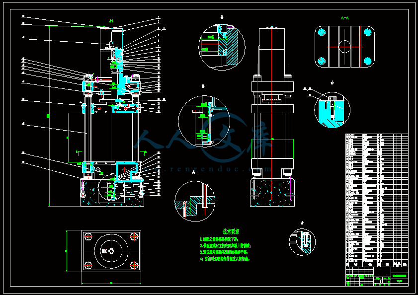
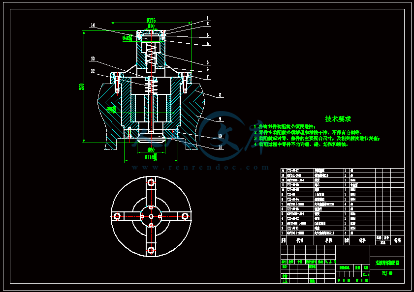


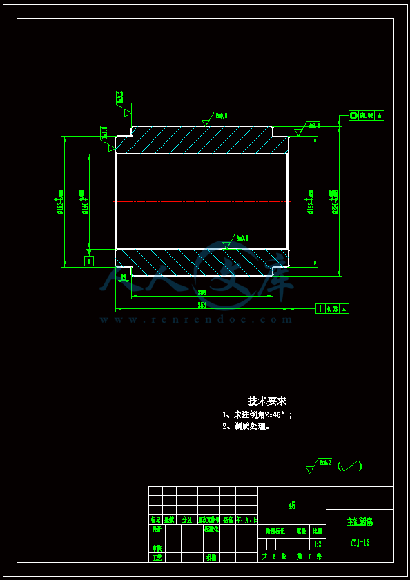
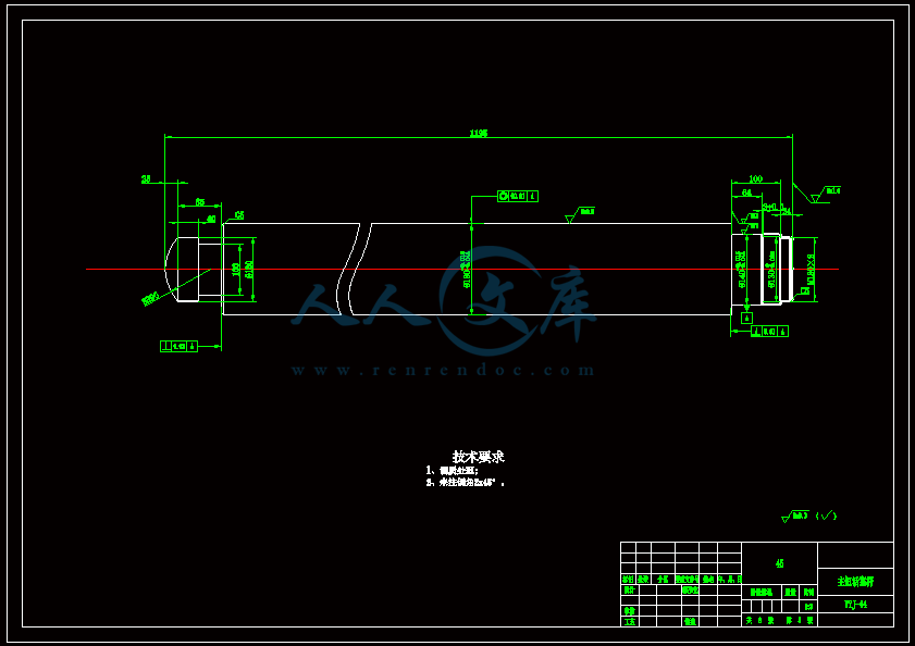


- 内容简介:
-
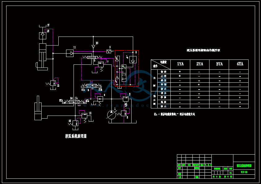
Four-column hydraulic press1.Four-column hydraulic press used Four-column hydraulic press for plastic materials in the pressing process. Products such as powder molding, plastic molding, cold (hot) extrusion of metal forming, sheet tension and transverse compression, bending pressure, turn through, correction. process2.Four-column Hydraulic Press Features Four-column hydraulic press with an independent power sector and the electrical system, using the button focus control enables adjustment, manual and semi-automatic three kinds of work: Four-column hydraulic pressure of work, pressing speed, load fast and slow down the schedule and the scope of may need to be adjusted according to process and can complete the top of the process, can take the top out of process, drawing process three kinds of process methods, each process has to be pressure, will be two-way action for the selection process, constant pressure molding process After the suppression of a delay with the top and automatic return. Four-column hydraulic characteristics. Four-column hydraulic press is the use of pressure compression forming objects. Is used to provide medium pressure hydraulic oil. Four-column hydraulic machine structure is simple and economical, practical. Appearance by octagonal shape. Four-column hydraulic press control electrical box with glass doors, PLC or computer control two general appliances, with reliable, reliable, direct action, and maintenance. Centralized control of the independent button. With the adjustment, his hands a single cycle of two kinds of operation mode. Four-column Hydraulic Press Hydraulic Control Valve can be used integrated system, and reliability, long life, small hydraulic impact, reducing the connecting pipe and the leak point, or common hydraulic control two. 3. Four-column hydraulic machine failure and maintenance of the common methods Four-column hydraulic machine failure and maintenance of the common methods: in the winter and the worse condition, should be ground on the four-column hydraulic system inspection, ground maintenance, oil change jobs often. Four-column hydraulic press work on the oil storage and transfer should be very much attention. Sheng drums plus special signs should be up and cover. In the winter, do not pay attention to the barrel while the result of the air condensed into water mixed with oil, not to be rusty rust bucket leather pieces into bins. Winter on the column hydraulic machine engine and other mechanical systems to the various preventive measures such as cover frost, heat insulation, for work with low viscosity oil, are suitable for hydraulic systems. In the Four-column hydraulic press hydraulic transmission system, are some of the more sophisticated parts. People on the four-column hydraulic machine hydraulic felt like labor-saving convenience, but at the same time feel that it is easy to damage. The reason is not clear column hydraulic main working principle and structure characteristics, which do not quite understand the preventive maintenance approach. Hydraulic system has three basic causative factors: pollution, over-heated and into the air. These three negative factors has close relationship, there any one issue, it will create another one or more related problems. From the practice shows that 75% of hydraulic system disease because, were caused by these three. 1, four column hydraulic press working oil into the dirt and deterioration due to 2, overheating 3 solution into the air: The Four-column hydraulic system some of the major precision parts cleaning and assembly, shall be carried out in a very clean room, indoor should be have clean floors and windows and doors closed, the temperature is best maintained at around 200C. 4. Four-column hydraulic machine common method of general maintenance Four-column hydraulic press common method of general maintenance (1) Four-column hydraulic press action, or failure of electrical wiring is not strong then check the electrical fault (2) Four-column hydraulic press slider creeping accumulation of air or a system, two precision air pump to adjust properly or check the pump suction column short of petroleum and an air intake pipe is then repeatedly pressurized two columns up and down movement and add oil, re- adjustment accuracy (3) Four-column hydraulic press with pressure when the slide slow down its support for excessive back-pressure valve to the cylinder to adjust the cavity without pressure, the maximum not more than 1MPa, four column hydraulic press, after stopping a serious one slipped under the brim slide 2 pressure valve seal ring leakage pressure adjustment is too small or the pressure I strictly an observation brim, hair oil deflated to adjust pressure Check Valve 2 5. Four-column hydraulic pressure gauge pointer swings a powerful memory with air pressure gauge oil line pipe mechanical vibration 3 2 1 on the pressure gauge when the damage slightly loosen the fittings, gas discharge tube card 2 will replace the pressure gauge in prison 3 6. Four-column hydraulic machine travel speed is not enough pressure, the pressure behind a high-pressure pump flow adjustment too small 2 pump wear or leakage of serious burns 3 system 1 according to the instructions to adjust pump, the pump in the eccentricity 25MPa adjustable adjusted to 5 Georgia 2 If the pump back to the oil port leakage is large, should remove the check 7. Four-column hydraulic packing pressure drop is too fast when 1 is involved in the packing of loose or pipe leaking valve 2-cylinder liquid-filled seal ring damage a check valve, keeping the pressure relief valve of the sealed joint case study 2 replacement seal ring 8. On the spiral column hydraulic machine On the spiral column hydraulic machine: This practical spiral column hydraulic machine, hydraulic machine in the field are involved, with special hydraulic screw drive, its mission is to provide a transmission device so that the main nut thread Zhi suppress the slide workpiece leverage, repression at the slider Fei workpiece trip, the main thrust nut from the role of hydraulic cylinders, so that oil pressure is sufficient to the spiral plane. The spiral column hydraulic machine, screw position in the central axis of the fuselage and through the bearings installed in the camera body, screw top and one inertia wheel connected to the main nut on the screw with the lower section of the main slide through the main flange and connected to one; nut with the screw midway through the Deputy Vice-flange and connected to one slide, spiral column hydraulic machine to the central axis of symmetry installation guide, the main slide, slide along the guide rail sliding connection vice, hydraulic cylinder to the central axis of body symmetry installed in the camera body, the hydraulic cylinder piston rod end of the slider hinge connection with the Deputy, can improve the nut, screw lubricating conditions, to extend the life of spiral column hydraulic machine. Hydraulic Four-column hydraulic machine on the station: Four-column hydraulic press hydraulic station works as follows: motor driven rotary pump, the pump suction from the tank after the Da You, the mechanical energy into hydraulic oil pressure to hydraulic oil through the manifold block (or valve combination ) is to achieve the direction of hydraulic valves, pressure, flow regulation by external piping after the transfer to the hydraulic cylinder or mechanical motor oil, thus controlling the direction of the transformation of liquid motivation, strength and speed of the size and promote a variety of hydraulic mechanical work. Four-column hydraulic press hydraulic station, also known as hydraulic pump station, is an independent hydraulic unit. It is required by the host oil supply, and control the direction of oil flow, pressure and flow, it applies to the host and the various hydraulic loading detachable column hydraulic machines. After the user purchases as long as the pressure points and the host will be the implementing agency (tank or oil motor) is connected with pipes, hydraulic machinery can achieve the various provisions of the movement, the work cycle. Four-column hydraulic press hydraulic station by the pump, manifold block or valve combination, fuel tank, electrical box combination. Function of each part as follows: Pump device - equipped with motors and pumps, it is the Four-column Hydraulic Press Hydraulic station power source, the mechanical energy into hydraulic fluid pressure energy. Manifold - hydraulic valves and passages from the assembled body. The implementation of its direction of hydraulic oil, pressure, flow regulation. Valve combination - is the plate valve installed in the stand-board, board after the tube connections, and integrated block the same function. Fuel tank - is half-closed container plate welding, also equipped with air filter oil filtering network and so on, it used oil, oil cooling and filtering. Electrical box - divided in two forms. A kind of set the external lead terminal board; one is equipped with a full set of control appliances. Four-column hydraulic pressure small what reasons: Four-column hydraulic pressure small reasons: 1. Four-column oil hydraulic cylinder dirty it? 2. Pressureout it? Pressure started? 3. Four-column hydraulic machine a long time, with the loose parts, within the vent it? 1, four column hydraulic pump wear serious leak within the major. 2, relief valve failure, is always open. 3, the direction of valve internal leakage big. 4, four column hydraulic press in the implementation of the original leak, suggesting a small pump pressure. Four-column Hydraulic Press Hydraulic Forming Process Applications Column hydraulic machine hydraulic forming process in the automotive, aviation, space and plumbing industries has been widely used, column hydraulic machine hydraulic forming process is mainly applied to: changes along the component axis round, rectangular, or shaped cross section hollow structural parts, such as car Special-shaped pieces of the exhaust system; non-circular cross section hollow frameworks, such as engine brackets, instrument panel frame, body frame (about 11% of car quality to 15%); hollow shaft and complex pipe fittings. About four column hydraulic press is not holding pressure problems. Q: Four-column hydraulic press is not up, start-up switch has 10MM action, increased and then not holding pressure, sliding body of work down, how is it? Answer: First check the column hydraulic pump outlet pressure, pressure control system, support valve is stuck. Piston down and the inferior vena not support force, not holding pressure may be four column hydraulic relief valve leakage. Four-column hydraulic press system is relatively simple, the first not considered too much trouble to repair Four-column hydraulic presses and pneumatic presses the difference between Four-column hydraulic presses and pneumatic presses, pneumatic machines have different noise power is small, and easy maintenance will not leak; column hydraulic machine quiet, strong and maintenance of little more complicated. Mainly depends on application. Steel plant noise already relatively large, and may from time to consider the noise factor. If the power requirements of larger, then select column hydraulic machine. If the strength requirement is not so big (50kg less bar) air pressure very good, also cheap. Four-cylinder in the hydraulic tension cylinder with fast speed up to 280mm / s, tensile strength up to 1000KN, BHF up 800KN, speed and pressure can be adjusted within the specified scope, the user can be required to pull extension speed and blank holder force selection to the best working condition, can be drawing a higher quality stainless steel and other products, is the ideal equipment for sheet drawing. The four-column hydraulic press hydraulic chamber fuel injection system required to meet the requirements of hydraulic forming process, while the system is not too complicated. Its action as follows: motor starter, oil pump to flow back into the tank by the valve in place, pump unloading. When 1DT power, the oil through the valve, check valve into the grease board will be pressed into the sheet metal forming die and. In forming the end, 1DT power, 2DT power, oil and grease through the pressure cylinder into the boards role in the high pressure under the sheet to further close the die and forming the small fillet. The Four-column hydraulic press hydraulic system is the key converter 5 and the pressure cylinder 10. Hydroforming, according to the needs of technology, hydraulic system provides hydraulic pressure chamber to flow and pressure of work should be constantly changing, so the hydraulic system The power consumption should also be working with the work flow and pressure changes constantly changingBefore embarking on the analysis of pressure transient phenomena and the derivation of the appropriate wave equations,it will be usefull to describe the general mechanism of pressure propagation by reference to the events fllowing the instantaneous closure of a value postioned at the med-length point of a frictionless pipeline carrying fluid between two reservoirs.The two pipeline sections upstream and downstream of the value are identical in all respects.Transient pressure waves will be propagated in both pipes by valve operation and it will be assumed that rate of value closure precludes the use of rigid column theory.As the valve is closed,so the fluide approaching its upstream face is retarded with a consequent compression of the flude and an expansion od the pipe cross-section.The increase in pressure at the valve results in a pressure wave being propagated upstream which conveys the retardation of flow to the column of fluid approaching the valve along the upstream pipeline.This pressure wave travels through the fluid at the appropriate sonic velocity,which will be shown to depend on the properties of the fluid and the pipe material.Similarly,on the downstream side of the valve the retardation of flow results in a reduction in pressure at the valve,with the result that a negative pressure waves is propagated along the downstream pipe which,in turn,retards the fluid flow.It will be assumed that this pressure drop in the downstream pipe is insufficient to reduce the fluid pressure to either its vapour pressure or its dissolved gas release pressure,which maybe considerable different.Thus,closure of the valve results in propagation of pressure waves along both pipes and,although these waves are of different sign relative to the steady pressure in the pipe prior to valve operation,the effect is to retard the flow in both pipe sections.The pipe itself is affected by the wave propagation as the upstream pipe swells as the pressure rise wave passes along it,while the downstream pipe contracts due to the passage of the pressure reducting wave.The magnitude of the deformation of the pipe cross-section depends on the pipe material and can be well demonstrated if,for example,thin-walled rubber tubing is employed.The passage of the pressure wave through the fluid is preceded,in practice,by a strain wave propagating along the pipe wall at a velocity close to the sonic velocity in the pipe material.However,this is a secondary effect and,while knowledge of its existence can explain some parts of a pressure-time trace following valve closure,it has little effect on the pressure levels generated in practical transient situations.Following valve closure,the subsequent pressure-time history will depend on the conditions prevailing at the boundaries of the system.In order to describe the events following valve closure in the simple pipe system outlined above,it will be easier to refer to a series of diagrams illustrating conditions in the pipe at a number of time steps.Assuming that valve closure was instantaneous,the fluid adjacent to the valve in each pipe would have been brought to rest and pressure waves conveying this information would have been propagated at each pipe at the appropriate sonic velocity c.At a later time t,the situation is as shown in fig.The wavefronts having moved a distance 1=ct,in each pipe,the deformation of the pipe cross-section will also have traveled a distancel as shown.The pressure waves reach the reservoirs terminating the pipes at a time t=1/c.at this instant,an unbalanced situation arises at the pipe-reservior junction,as it is clearly impossible for the layer of fluid adjacent to the reservoir inlet to maintain a pressure different to that prevailing at that depth in the reservoir.Hence,a restoring pressure wave having a magnitude suffcient to bring the pipeline pressure back to its value prior to valve closure is transmitted from each reservoit at a time 1/c.For the upstream pipe,this means that a pressure wave is propagated towards the closed valve,reducing the pipe pressure to its original value and restoring the pipe cross-section.The propagation of this wave also preduces a fluid flow from the pipe into the reservoir as the pipe ahead of the moving wave is at a higher pressure than the reservoir.Now,as the system is assumed to be frictionless,the magnitude of this reversed flow will be the exact opposite of the original flow velocity,as shown in fig.At the downstream reservoir,the converse occurs,resulting in the propagation of a pressure rise wave towards the valve and the establishment of a flow from the downstream reservoir towards the valve.For the simple pipe considered here,the restoring pressure waves in both pipes reach the valve at a time 21/c.The whole of the upstream pipe has,thus,been returned to its original pressure and a flow has been established out of the pipe.At time 21/c,as the wave has reached the valve,there remains no fluid ahead of the wave to support the reversed flow.A low pressure region,therefore,forms at the valve,destroying the flow and giving rise to a pressure reducing wave which is transmitted upstream from the valve,once again bringing the flow to rest along the pipe and reducing the pressure within the pipe .It is assumed that the pressure drop at the valve is insufficient to reduce the pressure to the fluid vapour pressure.As the system has been assumed to be frictionless,all the waves will have the same absolute magnitude and will be equal to the pressure increment,above steady running pressure,generated by the closure of the valve.If this pressure increment is h,then all the waves propagating will beh,Thus,the wave propagation upstream from the valve at time 21/c has a value-h,and reduces all points along the pipe to h below the initial pressure by the time it reachs the upstream reservoir at time 31/c.Similarly,the restoring wave from the downstream reservoir that reached the valve at time 21/c had established a reversed flow along the downstream pipe towards the closed valve .This is brought to rest at the valve,with a consequent rise in pressure which is transmitted.downstream as a +h wave arriving at the downstream reservoir at 31/c,at which time the whole of the downstream pipe is at pressure +h above the initial pressure whth the fuid at rest.Thus,at time 31/c an unbalanced situation similar to the situation at t=1/c again arises at the reservoir pipe junctions with the difference that it is the upstream pipe which is at a pressure below the reservoir pressure and the downstream pipe that is above reservoir pressure .However,the mechanism of restoring wave propagation is identical with that at t=1/c,resulting in a-h wave being transmitted from the upstream reservior,which effectively restores conditions along the pipe to their initial state,and a+h wave being propagated upstream from the downstream reservoir,which establishes a flow out of the downstream pipe.Thus,at time t=41/c when these waves reach the closed valve,the conditions along both pipes are identical to the conditions at t=0,i.e.the instant of valve closure.However ,as the valve is still shut,the established flow cannot be maintained and the cycle described above repeats.The period of the pressure cycle described is 41/c.However,a term ofen met in transient analysis is pipe period,this is defined as the time taken for a restoring reflection to arrive at the source of the initial transient propagation and,thus,has a value 21/c.In the case described,the pipe period for both pipes was the same and was the time taken for the reflection of the transient wave propagated by valve from the reservoirs.In the absence of friction , the cycle would continue indefinitely .However ,in practice, friction damps the pressure oscillations within a short period of time .In system where the frictional losses are high,the neglect of frictional effects can result in a serious underestimate of the pressure rise following valve closure.In these case,the head at the valve is considerably lower than the reservoir head.However,as the flow is retarded,so the frictional head loss is reduced along the pipe and the head at the valve increase towards the reservoir value.As each layer of fluid between the valve and the reservoir is brought to rest by the passage of the initial +h wave so a series of secondary positive waves each of a magnitude corresponding to the friction head recoverd is transmitted toward the valve,resulting in the full effect being felt at time 21/c.As the flow reverses in the pipe during time 21/c to 41/c,the opposite effect is recorded at the valve because of the re-establishment of a high friction loss,these variations being shown by lines AB and CD.In certain cases,such as long distance oilpipelines,this effect may contribute the larger part of the pressure rise following valve closure.Pressure transient propagation may be defined in any closed pipe application by two basic equations,namely the equations of motion and continuity applied to a short segment of the fluid column.The dependent variables are the fluids average pressure and velocity at any pipe cross section and the independent variables are time and distance,normally considered positive in the steady flow direction.Friction will be assumed proportional to velicity squared and steady flow friction relationships will be assumed to apply to the unsteady flow cases considered.四柱液压机一.四柱液压机用途四柱液压机适用于可塑性材料的压制工艺。如粉末制品成型、塑料制品成型、冷(热)挤压金属成型、薄板拉伸以及横压、弯压、翻透、校正等工艺。二.四柱液压机特点四柱液压机具有独立的动力机构和电气系统,采用按钮集中控制,可实现调整、手动及半自动三种工作方式:四柱液压机的工作压力、压制速度,空载快下行和减速的行程和范围,均可根据工艺需要进行调整,并能完成顶出工艺,可带顶出工艺、拉伸工艺三种工艺方式,每种工艺又为定压,定程两种工艺动作供选择,定压成型工艺在压制后具有顶出延时及自动回程。 四柱液压机的特点。四柱液压机就是利用压力使物体受压成形。提供压力的介质是利用液压油。四柱液压机结构简单、经济、实用。外观采用八角形状。四柱液压机控制电器箱采用玻璃门、PLC电脑控制或普通电器两种,具有工作可靠,工作可靠,动作直观,维修方便。独立按扭集中控制。具有调整、双手单次循环二种操作方式。四柱液压机液压控制可采用插装阀集成系统,动作可靠,使用寿命长,液压冲击小,减少了连接管路与泄露点,或普通液压控制两种。三.四柱液压机的常见故障和维护方法 四柱液压机的常见故障和维护方法:在冬季和较坏的工况下,要对四柱液压机系统勤检查、勤保养,常换工作油液。对四柱液压机工作油的储存和转运工作应十分注意。盛油桶应加专门的标志并掩盖好。在冬季,要注意桶内勿因空气冷凝成水分而混入油中,勿将桶皮生锈的锈片落入桶内。冬季对四柱液压机发动机与其他机械系统所采取的多项预防措施,如掩盖防冻、加热保温、换用低黏度工作油等,均适用于液压系统。在四柱液压机液压传动系统中,都是一些比较精密的零件。人们对四柱液压机的液压传动虽然觉得省力方便,但同时又感到它易于损坏。究其原因,主要是不太清楚四柱液压机工作原理和构造特性,从而也不大了解其预防保养的方法. 液压系统有3个基本的“致病”因素:污染、过热和进入空气。这3个不利因素有着密切的内在联系,出现其中任何一个问题,就会连带产生另外一个或多个问题。由实践证明,液压系统75%“致病”的原因,均是这三者造成的。1、 四柱液压机工作油液因进入污物而变质 2、过热3、进入空气 解决方法:对四柱液压机系统中一些主要精密件的清洗和装配,均应在十分清洁的室内进行,室内应有干净的地板和密闭的门窗,温度最好保持在200C左右。 四.四柱液压机常见的一般维修方法 四柱液压机常见的一般维修方法:(1)四柱液压机动作失灵 电气接线不牢或接错 检查电气 (2)四柱液压机滑块爬行 1 系统内积存空气或泵吸空2 精度调整不当或立柱缺油 1 检查泵吸油管是否进 气,然后多次上下运动并加压2 立柱上加机油,重新调整精度 (3)四柱液压机滑块慢速下行时带压 支撑力过大 调整背压阀使上缸上腔不带压,最大不大于1MPa,四柱液压机停车后滑块下溜严重 1 缸口密封环渗漏 压力阀调整压力太小或压口不严 1 观察缸口,发油放气2 调整压力检查阀口 五.四柱液压机压力表指针摆动厉害 1 压力表油路内存有空气2 管路机械振动压力表损坏 (1)上压时略拧松管接头,放气(2 )将管路卡牢(3)更换压力表 六.四柱液压机高压行程速度不够,上压慢: 1 高压泵流量调得过小2 泵磨损或烧伤3 系统内漏严重 (1)按泵的说明书进行调整,在25MPa时泵偏心可调调至5格(2)若泵回油口漏损大时,应拆下检查 7. 四柱液压机保压时压降太快 1 参与保压之各阀门不严或管路漏油2 缸内密封环损坏 (1)检查充液阀,保压泄压阀之密封研合情况(2)更换密封环 八.关于螺旋四柱液压机 关于螺旋四柱液压机:本实用型的螺旋四柱液压机,属于液压机领域,特别涉及螺旋传动的液压机,其任务是提供一种传动装置,使主螺母螺纹只在滑块压制工件时受力,而在滑块的非压制工件行程中,主螺母不受液压缸推力作用,以便让润滑油被充到螺旋承压面内。本螺旋四柱液压机,螺杆位于机身中心轴位置并通过轴承安装在机身上,螺杆上端与惯性轮联接为一体,主螺母配合于螺杆下段,通过主法兰与主滑块联接为一体;副螺母配合于螺杆中段,通过副法兰与副滑块联接为一体,螺旋四柱液压机内以中心轴对称安装导轨,主滑块、副滑块沿导轨滑动连接,液压缸以机身中心轴对称安装在机身上,液压缸之活塞杆端部与副滑块铰支联接,可以改善螺母、螺杆的润滑工况,延长螺旋四柱液压机使用寿命。关于四柱液压机的液压站:四柱液压机液压站的工作原理如下:电机带动油泵旋转,泵从油箱中吸油后打油,将机械能转化为液压油的压力能,液压油通过集成块(或阀组合)被液压阀实现了方向、压力、流量调节后经外接管路传输到液压机械的油缸或油马达中,从而控制了液动机方向的变换、力量的大小及速度的快慢,推动各种液压机械做功.四柱液压机液压站又称液压泵站,是独立的液压装置。它按主机要求供油,并控制油流的方向、 压力和流量,它适用于主机与液压装可分离的各种四柱液压机上。用户购后只要将压站与主机上的执行机构(油缸或油马达)用油管相连,液压机械即可实现各种规定的动作、工作循环。四柱液压机液压站是由泵装置、集成块或阀组合、油箱、电气盒组合而成。各部件功用如下:泵装置-上装有电机和油泵,它是四柱液压机液压站的动力源,将机械能转化为液压油的压力能。集成块-是由液压阀及通道体组装而成。它对液压油实行方向、压力、流量调节。阀组合-是板式阀装在立板上,板后管连接,与集成块功用同。油箱-是板焊的半封闭容器,上还装有滤油网空气滤清器等,它用来储油、油的冷却及过滤。电气盒-分两种形式。一种设置外接引线的端子板;一种是配置了全套控制电器。四柱液压机压力小是什么原因: 1.四柱液压机油缸的油脏吗? 2.憋压了吗?带压启动了? 3.四柱液压机时间长了,零件配合松了,内泄了? 1、四柱液压机泵磨损严重,内泄露大。 2、溢流阀出现故障,处于常开启状态。 3、方向阀内部泄露大。 4、四柱液压机执行原件内泄露大,显示泵压力小。 四柱液压机液压成形工艺的应用: 四柱液压机液压成形工艺在汽车、航空、航天和管道等行业有着广泛的应用,四柱液压机液压成形工艺主要适用于:沿构件轴线变化的圆形、矩形或异型截面空心结构件,如汽车的排气系统异型管件;非圆截面空心框架,如发动机托架、仪表盘支架、车身框架(约占汽车质量的11%15%);空心轴类件和复杂管件等。关于四柱液压机不保压的问题:问:四柱液压机不上升,起动上升开关有10MM动作,上升后不保压,工作滑体下滑,怎么回事?答:先检查四柱液压机泵的出口压力、控
- 温馨提示:
1: 本站所有资源如无特殊说明,都需要本地电脑安装OFFICE2007和PDF阅读器。图纸软件为CAD,CAXA,PROE,UG,SolidWorks等.压缩文件请下载最新的WinRAR软件解压。
2: 本站的文档不包含任何第三方提供的附件图纸等,如果需要附件,请联系上传者。文件的所有权益归上传用户所有。
3.本站RAR压缩包中若带图纸,网页内容里面会有图纸预览,若没有图纸预览就没有图纸。
4. 未经权益所有人同意不得将文件中的内容挪作商业或盈利用途。
5. 人人文库网仅提供信息存储空间,仅对用户上传内容的表现方式做保护处理,对用户上传分享的文档内容本身不做任何修改或编辑,并不能对任何下载内容负责。
6. 下载文件中如有侵权或不适当内容,请与我们联系,我们立即纠正。
7. 本站不保证下载资源的准确性、安全性和完整性, 同时也不承担用户因使用这些下载资源对自己和他人造成任何形式的伤害或损失。

人人文库网所有资源均是用户自行上传分享,仅供网友学习交流,未经上传用户书面授权,请勿作他用。
 川公网安备: 51019002004831号